MGA! Tech Talk – Basics of the MGA Electrical System and Fuse Requirements
 Tech Talk
with Bob Shafto, Technical Editor
Basics of the MGA Electrical System and Fuse Requirements
Let’s start with the nature of electricity and its interaction with components. Electrical components absorb or draw current, and only as much as they need to operate (based on overall resistance and the voltage applied). Current is a result of voltage across a resistance. If a short occurs in a component, it lowers the resistance, making it draw more current. The wiper and blower motors, solenoids and relays for instance, have windings of small gauge wire that might short together, lowering the resistance, causing it to draw more current than the small gauge wire can carry and burn out the component but not enough current to blow a fuse.
Power – The MGA has two power/current sources; the battery and the generator. Typically, the battery can supply over 300 amps and the C40 generator 22 amps. The battery’s only job is to start the car while the generator’s job is to keep the car running, and recharge the battery. If the battery fails or is dead, the car can be started using the crank handle or push start and will run on just the generator, until it is turned off. If the generator fails, the car will still start and run with just the battery but will eventually drain the battery. When the car is using battery power the ignition light on the tach is lit. The car will draw current from the highest voltage source. The battery will only draw current (charge) when the supply voltage (generator or battery charger) is higher than the battery voltage.
The regulator is intimidating to some, an ominous black box not to be disturbed, but is actually quite simple. It has two parts; one (cutout relay) is to connect or disconnect the generator output to the car electrical components when its voltage is higher than the battery, the other (regulator relay) is to control the output voltage. The generator output is fed back to the field coil, increasing the magnetic field around the armature which increases the output. The feedback is not a constant DC voltage but chopped (on and off) at about 600hz, creating an average voltage on the field coil which intern, controls the desired output voltage. If everything is on and the collective components require more power than the generator can supply, additional power will be drawn from the battery, which will eventually drain the battery. The ignition light won’t warn you when this is happening because the generator voltage and battery voltage will be nearly the same.
The ignition light does not have a ground connection. It has one side of the bulb connected to battery and the other connected to the generator output. The bulb will light when the difference in voltage is above a few volts and will be brighter as the difference increases. If the light is on when the ignition is off, the cutout contacts are closed and need adjusted or stuck together and need to be cleaned. This can damage the generator.
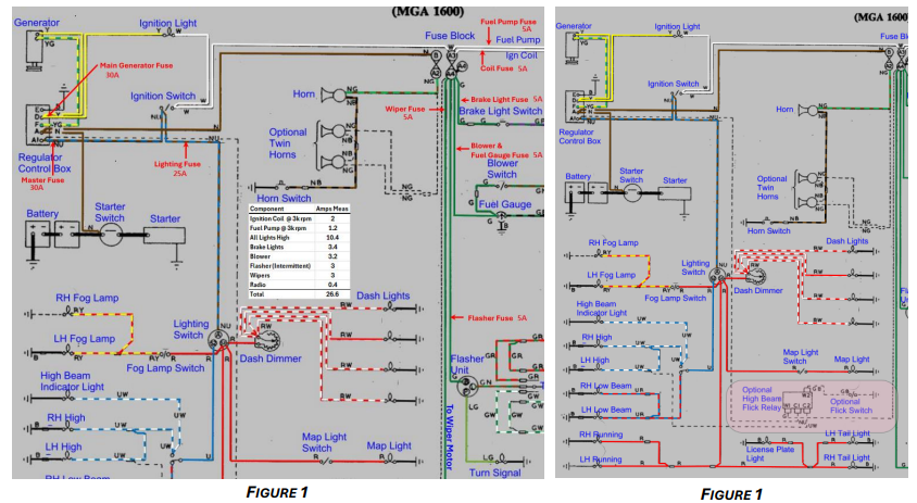
Power Distribution (Follow Along Figure 1)
A heavy cable connects battery power directly to the starter switch terminal and from there a 14-gauge brown wire connects to terminal A on the voltage regulator and to the horn fuse. The generator output is connected to terminal D on the voltage regulator with a 14-gauge yellow wire. The regulator terminal A1, is the combination of the battery and generator outputs and a 14-gauge brown with blue stripe wire connects it to the ignition switch and lighting switch. This wire feeds all the components in the car. The output of the ignition switch goes to the coil, fuel pump and terminal A3 on the fuse block. Terminals A4 (top fuse) feed brake lights, blower, fuel gauge, flasher unit and wiper motor. The result is that the ignition coil, fuel pump and all lights are unfused. This allows the car to be started and driven, day or night, without any fuses. The downside is that a short to ground in any of these circuits will draw extra current, melt wires and possibly cause fire. All the switches are designed to carry more than enough current for the components they are activating.
In modern cars we are accustomed to having most components on separate fuses so that a failure in one component does not take other components offline. If you want to take steps to improve the fusing or add other components (fans, audio lighting etc., please do so by making informed electrical decisions.
Things to consider
Adding a fuse for the already fused components (brake lights, blower, fuel gauge, flasher unit and wiper motor) doesn’t improve safety because they are protected by a common fuse and the components’ internal conductors are smaller than the harness wire and tend to fail internally. Individual fuses, isolate the components and circuits making diagnosing a fault a little easier.
Adding a fuse to the unfused components does improve safety, but should be done at the correct wire (Figure 1) and as close to the source terminal as practical. If you just want to protect the unfused components (mainly lighting), consider just adding a Master Fuse to terminal A1 of the regulator. This will protect all the previously unfused circuits.
Adding accessories
Extra electric fans, motors, solenoids, and lights should be wired similar to the optional high beam flick relay (Figure 2) (bottom right), using fused ignition to power the coil (fuse block terminal A4) and the 12v contact power coming from the starter switch battery terminal with an inline fuse. Audio equipment should be fused separately and as close to the source terminal as practical, being aware of the current on the car’s power and charging system. This bears repeating, “If everything is on and the collective components require more power than the generator can supply, additional power will be drawn from the battery, which will eventually drain the battery. The ignition light won’t warn you when this is happening because the generator voltage and battery voltage will be nearly the same. “ Don’t overdo the addons.
Adding a relay does not take the place of a fuse. A relay uses a low current coil to activate higher current contacts, so if you want to fuse the device the relay is driving, you need to fuse the contact incoming power not the coil.
Closing comments:
• Fuses protect wires not components.
• Most electrical fires are caused by pinched wires or poor connections, so pay close attention to wire routing and termination.
• Battery only supplies current when the generator output voltage is less than the battery voltage (mainly cranking or rpm below 1000).
Figure 1 below, shows possible points to be fused and the size of fuse to use. Personally, I would only add the Main Generator fuse and the Master Fuse directly off the regulator. That covers everything except the heavy battery cable and cable for the starter and leaves the car very well protected. Figure1, also includes current measurements made on my stock 1600, for each of the components. The fuel pump and ignition coil current draw, varies with RPM.