
MGA! Tech Talk – August 2025

 Tech Talk
with Bob Shafto, Technical Editor
MGA Crankcase Ventilation Test Review
In the winter of 2021, I was prompted to investigate the stock MGA crankcase ventilation and the controversy around the tappet vent function and flow. The results were somewhat surprising. As an automotive engine controls engineer, I have performed several hundreds of tests, studies and analysis over nearly 40 years, so the methodology was intuitive and the approach was pretty straightforward. Since completion, I have received many requests for how the test was performed and the reasoning. In this article I will focus more on the test than the results.
Air or airflow is driven by a difference in pressure, so measuring the pressure inside the air filter and at the tappet vent will reveal what is happening with the ventilation system. It is standard to begin testing by defining the system (determining the capabilities and limits of the components) so the first step was to evaluate the tappet vent tube.
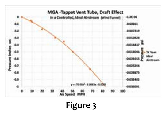
The graph can now be used as a tool to determine the amount of draft (low pressure) generated for any air speed around the bottom of the tube. Curve fitting of the data provides a formula, P = Figure 2-0.00007 * X2 – 0.0062*X – 0.0013 (where P = Pressure and X = airspeed) that can be used to calculate draft pressure from any air speed passing by the end of the tube; same method used in modern cars (Figure 3).
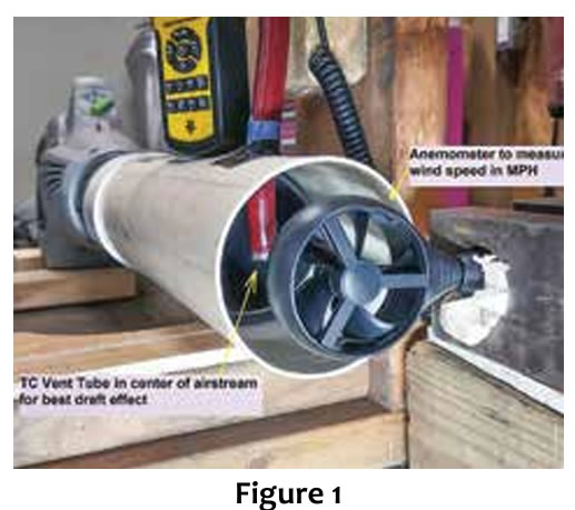 By placing the lower 1 1/2-inch of the tube in a 4-inch diameter PVC drain pipe with an anemometer (device for measuring air speed) on the output and a leaf blower sealed to the input, I can control the air speed and accurately measure airflow moving past the vent tube. Placing a manometer (device for measuring pressure) in the top and bottom of the tube allows measurement or mapping of the draft effect (low pressure or suction) created by air flowing past the end of the tube (Figure 1).
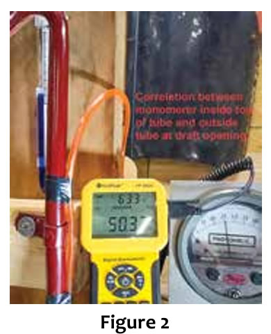
An engineering grade Dwyer pressure meter was also used for redundancy, accuracy and data correlation. Then data was collected from 0 to 70 MPH and plotted on a graph (Figure 2).
 The next component to test is the air filter chamber. The original Vokes cover was replaced with a Plexiglas disc with a pressure port. The Dwyer pressure meter was attached to the pressure port and pressure readings were taken at every 1000 RPM. This reading will depend slightly on the type and condition of the air filter. For air to flow through the filter there must be a difference in pressure, inside versus outside. In this test, a clean, unoiled, original-type air filter was used. A dirty or more dense air filter will develop a lower pressure (more suction) and a more porous or less dense filter will create higher pressure (less suck).
 Data was taken with the air filter port blocked to get the lowest pressure (most suction), with the port directly open to atmosphere (least suction), normal connection to rocker cover and normal connection but with the tappet vent plugged. This last condition is interesting because it reveals the blow-by pressure. With the tappet vent plugged (no access to atmosphere), the data should match the plugged air filter port data, but it doesn’t because blow-by is adding pressure to the system. Therefore, the difference between plugged air filter port and plugged tappet vent is blow-by pressure pushing gasses out of the crankcase. Notice that the difference is almost constant because as engine speed increases, the blow-by pulses get shorter but more frequent (Figure 4).
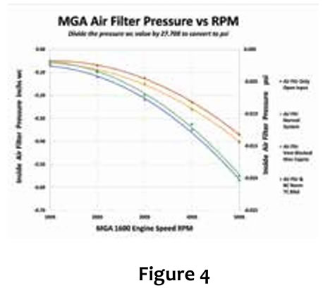 As expected, the highest pressure (least suck) is when the air filter vent is directly open to atmosphere (brown curve). When the air filter and rocker are connected (orange curve), the pressure is a little lower because the path to atmosphere is further away and slightly restricted. Pressure in the entire system is the same, much like placing an attic fan in the ceiling to draw air out of the house and into the attic. The pressure everywhere inside the house will be the same, but slightly lower than atmosphere. The pressure in the entire attic will be higher than atmosphere, pushing air out the roof vents. If you open a door or window, the pressure inside the entire house will increase a little. Flow will be the most direct path from opening to fan. A room not in the direct flow path will have no flow.
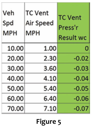
The next step was to test the tappet airflow while driving from 0 to 70 MPH by mounting the anemometer behind the tip of the vent tube. The airflow around the vent tube was only 10 percent of the vehicle speed (Figure 5).
 This was the surprising part. I expected the vent tube to experience more airflow than it actually did because my thinking was based on intuition and didn’t consider the physics. Examination of the placement of the bottom of the vent tube made it clear that the vent tube opening is about 3 inches above the airstream under the car and blocked by the front crossmember and suspension so it doesn’t get the airflow from under the car. The faster you go the more streamlined the airstream under the car becomes and even less likely for airflow to surround the vent tube.
At one point during the driving test I took advantage of a long, steep downhill grade by shifting to neutral and taking my foot of the accelerator pedal at 60 MPH and the airflow meter went to zero. When I pressed on the accelerator again, the meter responded and as I increased and decreased the pedal, the meter followed, indicating that the air from the radiator fan provided more airflow around the vent than the airstream under the car. I also took pressure data at the tube opening and the air filter during the road test revealing that the relative pressure in the air filter was lower than the pressure at the vent tube by 0.09 in wc to 0.34 in wc, depending on engine RPM and vehicle speed.
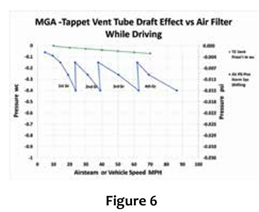 The data was taken while driving from 0 to 70 MPH, green data is the tappet vent tube and the blue is the air filter data, dependent on RPM, so it appears as a saw tooth as accelerating to 5,000 RPM and shifting through the gears. The final result is that the air filter chamber will always have a lower pressure than the tappet vent. System flow is, vent tube to air filter (Figure 6).
There is one exception. When the throttle is wide open and the accelerator pedal is released (throttle closes suddenly) a shock or pressure wave travels back into the air filter chamber, momentarily increasing the pressure. A gradual release of the throttle does not create back pressure.
Here is a video of the tappet vent during this drive showing a 1-inch piece of yarn that was sucked into the tube at engine start and remained there from 0 to 70 MPH:
photos.app.goo.gl/6itf2MbiFhD8Cv1e6