
MGA! Tech Talk – MGA Generator Rebuild
 Tech Talk
with Bob Shafto, Technical Editor
The generator is a critical part of the MGA operating system, supplying all the car’s electrical power while driving. It works by rotating the armature in a magnetic field (field coil) which induces power into the armature windings through the brushes to the output terminal. The voltage control is provided by the regulator control box which controls the power applied to the field coil. The Lucas C40 generator was original equipment on all MGAs and designed to last fifty thousand miles before needing repair or rebuild. Rebuilding the generator might sound intimidating but is actually straight forward and not difficult at all. If you have a replacement generator, the bearing ends may differ but the rebuild procedure is the same.
https://forum.lrsoc.com/forum_files/Lucas%20Manual%20A6.pdf
Disassembly
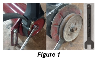 The first step is to remove the front pulley and fan. The pulley has to be held stationary to remove the nut so the back side of the pulley hub is square to fit a thin 7/8″ wrench. (I made one from 14 GA mild steel plate 8″ to 10″ long with a 15/16″ square open end in a 2″ wide head and a 7/8″ wide handle.) If an appropriate wrench is not available, a strap wrench also works to hold the pulley while using a 11/16″ wrench on the nut. (Figure 1)
Removing the pulley might take a little effort and maybe some penetrating oil. After removing the pulley, the fan should pull off over the key in the shaft. Remove the key by placing a screwdriver under the front edge and tap handle with a hammer. Clean the key with 240 or finer grit sandpaper.
Turn your attention to the brush end of the generator and remove the two screws holding the generator endcaps/mounting plates in place, then use a thin screwdriver in the seam where the case and mounting plate meet. Tap the screwdriver handle with a hammer to separate the mounting plate from the case, then remove the mounting plate.
Remove the front mounting plate with armature attached by separating it from the case in the same manner as the rear mounting plate.
Cleaning and inspection
Clean everything with compressed air and inspect for damage or wear. Spin the mounting plate on the armature back and forth to ensure the bearing runs free and smooth with no cogging.
If the bearing needs to be serviced, the mounting plate can be removed by supporting the mounting from the underside and pressing the armature shaft out of the bearing. Be careful to support the mounting plate properly; it is cast aluminum alloy with several ventilation holes. If not supported correctly, it could crack or break.
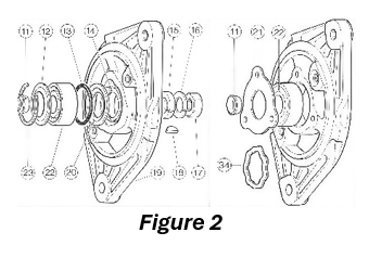 The bearing on this end is usually a ball type bearing held in with a circlip but some versions have an end plate riveted to the inside of the mounting plate and a sealed bearing. In this case the rivets can be removed and replaced with screws. (Figure 2)
Clean the open face bearing with mineral spirits or fuel oil and blow dry with compressed air. Inspect the bearing again for rust, dirt and free running with no cogging. Also inspect the bearing face plates, O ring and felt ring (replace if necessary). If the bearing runs smoothly, pack with high temperature wheel bearing grease and reassemble. The bearing (17H5043) is a standard15mm × 35mm × 11mm ball bearing. If the bearing needs to be replaced, use the same type as original (open face or sealed). If you choose to use a sealed bearing, a shim will be required to compensate for the bearing cover plates, O ring and felt ring in the original design.
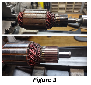 Clean the armature commutator and shaft ends by mounting and spinning in a lathe, drill press or drill. (Figure 3) Use a folded 600 grit sandpaper on the copper commutator and shaft while it is spinning at high speed to remove oxide, scratches and ridges. After cleaning the commutator, clean between the commutator segments with a bamboo skewer, toothpick or ty-wrap.
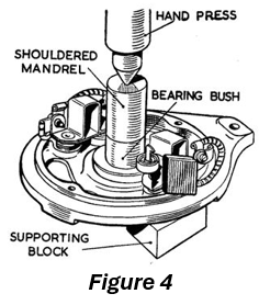 Inspect the rear mounting plate, brushes, brush springs and bushing. New brushes are 11/16″ long and anything less than ½″ should be replaced. The bushing should be free of dirt/grime and free from scratches or ridges and measure 0.592″ to 0.597 ID. New bushing should measure 0.872″ long, 0.714″ OD and 0.595″ ID. Brushes, bushings and bearings are available at the usual MG and Lucas suppliers as well as some auto parts stores. If the rear bushing needs to be replaced, it is best to press it out but be sure to place support blocks where the two 6″ assembly screw heads go to avoid cracking or breaking the end plate. This will also push out the oil cap and felt oiler. (Figure 4)
Another way is to screw a large tap into the bushing enough to get a good grip but not so deep that it will exit the bushing and damage the felt oiler. Then clamp the end of the tap in vise and carefully drive the plate off the bushing. Soak the new bushing in oil for 24 hours before installing it into the mounting plate.
Reassembly
Start by assembling the front (pulley end) mounting plate as shown (Figure 2) then press the plate onto the armature shaft until fully seated. Slide the armature with attached mounting plate into the case and align the ball on the edge of the mounting plate to the notch in the edge of the case and tap into place. This is the ground connection to the generator so be sure the mating surfaces are clean, bare metal.
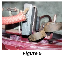 To assemble the rear (brush end) mounting you must first retract the brushes and place the curled spring end against the brush and edge of brush holder. (Figure 5) Then drip several drops of 30 SAE oil into the felt pad behind the bushing until the felt is saturated. Place the mounting plate on the armature shaft, align and tap into place. Again, the mating surfaces must be clean, bare metal. Insert the 6″ assembly screws and tighten.
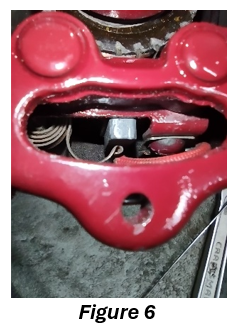 The next step is to set the brush springs onto the back of the brushes using a small screwdriver or a right-angle dental pick, through the opening in the mounting plate behind the brushes. (Figure6)
Now is a good time to mask and paint the generator if you wish.
Finally, after straightening any bent fan fins, it is time to install the distance spacer, fan, woodruff key, pulley, lock washer and nut. Check that the pulley spins free and smooth.
Final check
Connect a 12v power source (charger, battery or power supply) to the generator according to the car’s ground polarity (negative ground = negative lead to mounting plate, positive ground = positive lead to mounting plate) then briefly touch the other supply lead to the F (field coil) terminal. You should get a spark. This will polarize the generator for your application. Now connect the F and D terminals together and attach the lead to either terminal for a couple seconds, and the generator should run like a motor. This ensures that the brushes and internal wiring are good.