
Alternator Conversion for the MGA

VOL 26/NUMBER 1
 During another GT-25 parking lot conversation, it was mentioned that someone in California was making a bracket to mount a Lucas alternator on the MGA engine.
I had covered my own alternator conversion about four years ago in MGA! (Volume 21, Number 5), so I decided I would locate and buy the bracket and re-run the conversion article. I found a bracket with my first contact – British Automotive of Novato, California. The price was about $25, including shipping. The bracket is part of an alternator conversion kit that British Automotive sells for the early MGB. Their kit, which includes the Lucas alternator, should fit the MGA, but their wiring instructions for the early MGB may need some interpretation for the MGA. British Automotive can be contacted at (415) 883-7200, or through their website.
Since I had installed an alternator in my MGA when I wrote the previous article, I purchased just the bracket to replace the threaded rod I had used for the previous installation.

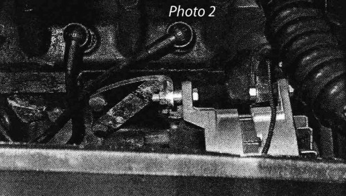
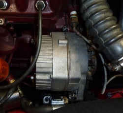
The two accompanying photographs show the threaded rod installation (Photo No. 1), and the new installation with the bracket (Photo No. 2). I think you will agree that the bracket looks much neater – as if it belongs there. The threaded rod might have caused a bit of stress or vibration on the mounting bracket attached to the water pump, because when I went to remove the rod I found that the water pump bracket had broken. For the photograph, the broken part of the water pump bracket is just resting in place, and I will have to replace the water pump before I can drive the car again!
I will now repeat my previous article on the conversion, updated for the use of the special rear bracket. Also, last time, as subsequently pointed out by Blake Urban of Aberdeen, South Dakota, I omitted to mention that the car’s electrical system must be wired with negative ground.
The main advantage of replacing the original equipment generator with an alternator is the ability to run more electrical accessories without depleting the charge on your battery, particularly during those dark winter months when higher-powered lights could be a distinct advantage. The use of the alternator also eliminates the potentially troublesome generator brushes and voltage regulator. The MGB Lucas alternator is the most suitable replacement because other than being about two thirds the length, it mounts in exactly the same way as the original generator. Both the Lucas generator and alternator are mounted by in-line lugs on the end plates, with an additional belt tension adjuster lug on the front plate that is spaced 90 degrees from the mounting lug.
At the front end, the installation of the Lucas alternator is exactly the same as the generator. The mounting lug is attached to the bracket on the water pump, and the original adjuster bracket is attached to the other lug to tension the fan belt. In this position the alternator pulley aligns perfectly with the fan belt. However, with the alternator mounted at the front, the rear plate-mounting lug is a couple of inches short the rear-mounting bracket attached to the engine block. This is where the bracket from British Automotive comes in. The bracket is attached to the engine at the same point as the original generator bracket, but is shaped to reach forward about two inches to meet the rear of the alternator allowing it to be mounted in the same manner as the original generator. The two mounting bolts that attach the rear bracket to the engine have slotted holes in the bracket. These two bolts are tightened last so that the alternator does not stress the water pump bracket at the front.
With the mechanical installation complete, the next step is the electrical connections and modifications. Lucas alternators for the MGB all have an internal voltage regulator, but have several different connector layouts at the rear. However, all styles of alternator provide one or more terminals to connect to the battery circuit and one terminal to connect to the ignition light. Some of the earlier alternators have a couple of terminals that need to be jumpered together. Basically, the later the alternator the simpler the connections.
The particular alternator I have used is a later model with two large spade terminals for output to the battery circuit, and a smaller, regular size, spade terminal between them for the ignition light. I was going to use an alternator connector from an old MGB wiring harness, but none of my old harnesses had the matching connector for the alternator I was using. Incidentally, an old MGB wiring harness is a useful source of a variety of color-coded wire and Lucas connectors. So, instead of a matching plug, I used separate matching spade terminal connectors from the local auto parts store. For electrical hook-up, I decided that using the existing wiring would make for the easiest and neatest installation. This included leaving the voltage regulator in place, but inoperative, as a convenient terminal strip.
The original generator installation has two basic circuits, one for voltage output and one for field excitation and output control. The output circuit consists of a thick yellow wire from the D terminal on the generator to the D terminal on the regulator, and a thick brown wire from the A terminal on the regulator to the battery via a terminal on the starter switch. All of the car’s electrical circuits are then supplied from the A terminal or the Al terminal on the regulator. The AI terminal is used for the heavier current items to provide current load sensing within the regulator. The voltage to the electrical circuits is regulated by the regulators control of the field voltage supplied to the generator. The field control is provided by the thin yellow/green wire from the F terminal on the regulator to the F terminal on the generator. The ignition light circuit is provided by a thin yellow wire from the D terminal on the regulator to the ignition light.
The alternator installation requires the same two circuits, with the difference that the alternator output voltage is already regulated and requires no external voltage regulator. The basic modification for the output circuit then requires that the voltage regulator be removed from the circuit, and that the output terminal(s) from the alternator be connected directly to all the wires that originally connected to the A and Al terminals of the regulator. The ignition light circuit requires a direct connection from the alternator terminal to the ignition light. I accomplished these required circuit modifications using the existing wiring in the following way.
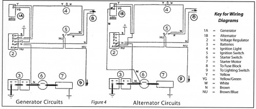
A large spade connection is attached to the thick yellow wire that originally connected to the D terminal of the generator, and this wire is then connected to one of the output terminals on the alternator. The other end of this thick yellow wire is removed from the D-terminal on the regulator and connected to the A1 terminal on the regulator. The existing brown wire on this terminal provides the connection to the battery via the terminal on the starter switch. An additional thick brown alternator circuit wire from the old MGB harness is connected from the other output terminal on the alternator directly to the starter switch. A large spade terminal is attached at the alternator end and a large eye terminal at the switch end. If you do not have an old MGB wiring harness, this wire should be 10 or L2-gauge. A piece of solid, I0-gauge copper wire is used as a jumper between the A and Al terminals of the voltage regulator. A regular spade connector is attached to the thin yellow f green wire that originally connected to the F terminal of the generator, and this wire is then connected to the ignition light terminal on the alternator. The other end of this thin yellow/green wire is removed from the F-terminal on the regulator and connected directly to the thin yellow wire that was originally connected to the D-Terminal on the regulator, using male and female spade connectors. The existing thin yellow wire now provides the connection to the ignition light. The wiring diagram shows the overall wiring modifications.
This completes the wiring modification. Although the voltage regulator is still in place, it is inoperative, with no connections to the D and F terminals and with the A and AI terminals jumpered together. The only additional wire is the thick brown wire from the alternator to the starter switch. This additional wire should be taped to the outside of the existing wiring harness.
My alternator installation was on our MGA 15OO Coupe, which, like all l500s, has the coil mounted on a bracket attached to the generator. The alternator is just a little bit fatter than the generator, so the band for the coil-mounting bracket would not quite stretch around it. It is possible that the band could be modified to fit the alternator, but there was a hole in the inner fender close by, so I chose to mount the coil there. It remains there attached by one hole, and has done so for four years. It is still my intent to either drill a second hole for more secure mounting, or to acquire a coil mounting bracket for the later 16OO or 1600 Mk II to attach to the motor mount.
Comment by: Mike Ash
Joe: I don’t have any experience with the Mini Denso, but I believe it is a direct replacement for the Lucas item. If so, it should work. The bracket isn’t very expensive, so I would suggest giving it a try. Mike.
Comment by: Joe Schandl
Mike , Will the moss bracket work with a Mini Denso 50 amp alternator.Thank you for your input. JOE
Comment by: Mike Ash
Moss supplies the conversion bracket as a separate item. It is shown in the front section of their MGA catalog. It is also the origial bracket for the MG Midget with A-series engine and alternator.
Comment by: Michael Phillips
Unfortunately the British automotive website states they are no longer marketing any of their specialized parts. So time to find another supplier or make your own bracket.
Comment by: John Daley
Very easy to follow directions (I say this because I can understand all the words). I am brand new to NAMGAR. I look forward to asking lots of questions.
I have been restoring a 1960 MGA Coupe for about a year. This is my first frame off restoration. I do not have a completely original MGA so I am making several updates and modifications, i.e., 1966 MGB rebuilt engine and a 1963 overdrive transmission. I initially set up an alternator conversion using a GM alternator, adjustment arm, and similar rod as shown in your picture. I have since opted to use a Mini Denso 50 amp alternaotr, mainly because the Denso is very small, simple to wire, fairly easy to mount, and light weight.
Anyway, I find you article very useful, thank you.
John
Comment by: Marc Vadenais
I found this tech article very well written and easy to comprehend and implement. I read as many articles on this conversion as I could–especially about the wiring changes. There were contadictory wiring instructions in most of the articles, but this one was the only one that worked perfectly! Well done.