
Converting the Electrical System to Negative Ground
 Some MGA owners have tried to install a modern radio/CD player, or to use a GPS, which is helpful for touring today. As the MGA is originally positive ground (positive battery terminal connected to chassis), this can be a problem. A solution is to convert the electrical system to negative ground. This is a simple process which Mike Ash described in Volume 18, No 4 of MGA! Magazine. As an introduction to this topic, he also covers the installation of a radio, speakers, and an antenna.
VOL 18/NUMBER 4
FITTING A RADIO
In the Open Fire section of the last issue of MGA!, James Michel of Lombard, Illinois, asked about fitting a radio in an MGA. His principal problem being that of installing a negative ground radio in a positive ground system. The most obvious way to solve the problem is to convert the MGA electrical system to negative ground, which is the subject of the next topic.
The purists out there who want to retain the original positive ground system can consider the use of a 12-volt to 12-volt inverter which will provide a 12-volt floating output, either side of which can be connected to ground. The disadvantage of the inverter is that it costs money and it emits a high-pitched whine which can become very annoying. Another solution for the purist is to isolate the radio chassis from the car body and chassis. The disadvantage of this is that the entire radio case, including any metal on the front panel, is live at 12 volts, with the potential of shorting out. Of course, the real purist would use a period AM, mono-channel, British-made radio that is wired for use in a positive ground system.
However, if you are not a purist, the best and no-cost solution is to change the car’s electrical system to negative ground. With a negative ground system, there is no limit to the sound system that can be installed in your MGA. However, in really extreme cases of a super high-power audio system, the 20-amp capacity of the generator may oblige a choice between the sound system and headlights when driving at night!
As mentioned for the purists, the original sound system for the MGA was intended to be a 1950’s style mono-channel, AM radio. The radio mounted in the slot in the dashboard, and an accessory speaker kit mounted behind the dashboard to direct the sound out through the central grille. Unless you are going in for the aforementioned super high-power audio system, an adequate modern radio can still be mounted in the radio slot in the dashboard, but I would suggest some alternative to the single central speaker. Possible locations for stereo speakers are in the side kick-panels ahead of the doors, in the door panels or, in the case of the coupe, in the rear shelf. The choice is yours, but I would suggest that, because of the interior noise level in an MGA, you select a location where the speaker sound has a fairly direct path to your ears. I have a 1969 MGB where the standard speaker location is under the dashboard, with the sound directed downward toward the floor on the passenger side. Such an arrangement requires higher volume levels to make the sound audible to the driver!
For the antenna, I would suggest the retracting kind, either manual or power, mounted on top of the right front fender, just ahead of the windshield. If you remove the splash panel in the fender, you will see that there is quite a large cavity to accommodate the underside of the antenna. I suggest the retracting type of antenna so that it does not interfere with the fitting of a car cover. If you do not wish to drill the necessary hole in the top of the front fender, then the antenna can be mounted on a bracket attached to the rear bumper mounting. This will probably require a longer coaxial lead than is normally supplied with an antenna, and the lead may be too long for the range of the antenna tuning adjustment on the radio.
 NEGATIVE GROUND
As promised, this is a follow-up to the previous topic. I originally wrote on this subject way back in MGA!Volume 13, Number 5; which, incidentally, was my first technical article for MGA! Have I really been doing this since 1988? Anyway, this is basically a rerun of that article, with a few changes. Last time, I said that the connections to the terminals of the gas gauge would have to be switched, but I believe I have subsequently determined that this is not the case. So the gas gauge has now been omitted from the list of affected items. With so many new members joining NAMGAR, this topic, and others, was due for an airing, anyway!
Of the original MGA electrical components, only three are affected by the polarity of the ground system. These three are: battery, generator, ignition coil. The remaining original electrical items, such as the regulator, fuel pump, gas gauge, starter motor and wiper motor are not affected by voltage polarity. The following is a step-by-step procedure for changing the ground polarity.
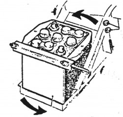
- Disconnect the battery cables, starting with the ground cable, of course. Turn the batteries (or battery if you have a single 12-volt) around. Reconnect the primary cable (the long one from the starter switch) to the positive terminal of the battery of the single 12 -volt battery, or to the positive terminal of the 6-volt battery in the right side battery carrier. If you have the two 6-volt batteries, connect the negative terminal of the right side battery to the positive terminal of the left side battery. Do not connect the ground cable at this time. While you are changing the battery cables, you will notice that the battery terminals are different diameters, and you may have to purchase new cables, or at least new cable ends, if they cannot be made to fit. For the twin 6-volt system, you can turn the cable between the two batteries around so that it will still fit the terminals.
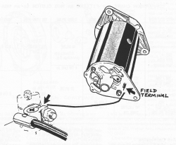
- Disconnect the wire from the field terminal of the generator, or dynamo, as they say in the U.K. The field terminal is the smaller of the two terminals on the rear plate of the generator. Depending on the vintage of your particular generator, it is either the one with the smaller stud, or the one with the smaller spade connector.
- Reverse the connections on the primary side of the ignition coil. Original MGA Lucas coils were intended for positive ground installations, and the terminals were marked “SW’, for ignition switch, and “CB”, for contact breaker (distributor points). These should now be reconnected so that the “CB” terminal has the lead from the ignition switch, and the “SW’ terminal has the lead to the distributor. On later Lucas coils, the terminals were marked “+” and “-“, and the “+” terminal should now be connected to the lead from the ignition switch, and the “-” terminal to the lead to the distributor.
- Now connect negative (ground) lead to the battery.
- The final step is to re-polarize the generator by “flashing the field.” No, don’t reach for your raincoat, but temporarily hold the bare end of a piece of insulated wire to the generator field terminal, and momentarily touch the other end of the wire to the positive terminal of the battery. Of course, you would need a rather long wire to reach the battery from the generator, and you could not hold both ends at the same time anyway. So instead of actually taking the wire all the way back to the battery, use the battery cable terminal on the starter switch. When you momentarily touch the wire to the battery cable terminal, you should see a spark. Do it a couple of times to be sure. The purpose of this is to reverse the direction of the residual magnetism in the field poles of the generator, thereby reversing the direction of current flow from the generator when it is driven by the engine.
That is the end of the procedure. Simple, isn’t it! Now, if you have some other non-original electrical items fitted to your MGA, they may also need to have their connections reversed. Such items might be a solid-state fuel pump, a two terminal plastic replacement fuel pump, an ammeter or battery condition meter, etc.
Comment by: Gilbert Clark DuPre, Jr
Yes you can put one 12 v group 26 or 26a battery in the passenger side box. Then move the red grond wire over to a spot on the side of the box. Since my last input I converted to negative ground. I would convert its so much easier to put modern radio in and other charging things.
Comment by: James W Johnson
I’m ok with the positive ground but want to convert to a 12 volt battery from the two 6 volt. Can I simply replace the two and rewire to a 12? Thanks. Jim Johnson
Comment by: Gilbert Clark DuPre, Jr
I still have positive ground. For my GPS other aux devices with negative grounds, I installed a plastic aux receptacle under my dash with the center post connected to the the body and the outer prongs to the brown wire on the fuse block. I also put a 5 amp inline fuse in the positive side. I guess I could plug a small boombox with a cd in it also and probably get some good radio stations.
Comment by: Gilbert Clark DuPre, Jr
If you have a solid state fuel pump install on the positive ground you will have to modify it to work on negative ground.