
MGA/Magnette Choke Cable & Lever Adjustment

VOL 20/NUMBER 2
 Having spent some little time investigating the adjustment of the carburetor choke levers, I have come to the conclusion that it is a relatively straightforward task.
The problem appears to be one of accessibility when the carburetors are installed in the car rather than any mechanical limitations. Magnette owners should have little or no problem, but on the MGA the hood opening leaves Iittle room to make the adjustment or to see the effects of those adjustments. A tolerance for skinned knuckles will help the former and an inspection mirror, the latter. To aid in my understanding of the problems, I dragged a pair of MGA SU carburetors out of the attic and mounted them on a manifold. Which, of course, made everything much easier than if they were installed in the car! However, as a check, I reviewed the operation on our MGA Coupe, and confirmed what I have written here.
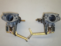
First, it is critical that all of the component parts are present and in good condition. The accompanying Figure 1 clearly shows all of the correct parts in their correct locations. For the choke levers themselves, it is particularly important that all pivot holes, marked A through F, have little or no wear, and that the pivots (clevis pin or other) that pass through them also have little or no wear, and are a snug fit. Any appreciable slack at these points can adversely affect the adjustment and create the need for a considerably longer pull on the choke lever. For the pivot points at G and H, however, the pivot hole should be quite a bit larger than the clevis pin, as will be explained later.
Principle of Operation
As always, a discussion of the principle of operation will aid in the understanding of the adjustment requirements. The ultimate purpose of the choke levers is to respond to the pull on the choke knob on the dashboard by pulling the carburetor jets, attached at pivot points A and F, down out of the jets assembly to richen the mixture for cold starting of the car. An additional purpose is to provide a “fast idle” in response to the initial movement of the choke knob. The choke knob is connected via cable to a fitting, not shown, that is attached to point E on the choke lever of the rear carburetor. Pulling on the choke knob pulls on the choke cable which, in turn pulls upward on the rear carb choke lever. With this upward movement at the end, the lever rotates about the point G to create a downward movement at the point F. The downward movement at F pulls the jet down to richen the mixture in that carb, and a spring at the end of the lever returns the jet to its original position when the choke knob is pushed back in. A link, item 2, is attached at point D to cause the choke lever on the front carb to move in a similar manner.
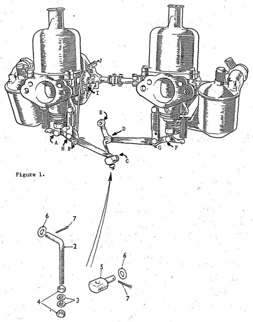
Now, the pivot holes at G and H are slightly enlarged so that the initial upward movement at E, in response to the pull on the choke cable, moves both of the levers in unison to take up the slack in these holes, without causing any movement of either jet. If this slack were at any of the other pivot points, such movement would be wasted and detrimental to the operation of the choke system; but here it serves a purpose. On the front carb, the choke lever is connected to an arm at point B which rotates a cam, item I. An adjuster screw, item J, which is part of a lever on the throttle shaft, acts on the edge of the cam such that movement of the cam can slightly change the throttle opening at idle, and control the idle speed. During the initial movement of the front choke lever to take up the slack at H, the lever at B moves and rotates the cam. Thus, the initial pull on the choke lever provides for a faster engine idle, without applying any choke. This enables the driver, after starting the car with the choke, to shut off the choke as soon as practicable, while retaining a slightly faster idle speed to prevent stalling until the engine is fully warmed up.
Choke Adjustment
So much for the theory of operation, now how do we adjust the choke levers. Well, the adjustment procedure is as simple as that described in the shop manual, if you can get to the adjustments and see what you are doing at the same time! First, of course, the air cleaners should be removed; and they will have been if the adjustment is to be performed subsequent to a tune-up and carb adjustment. Once the accessibility problem is overcome, the main difficulty is to attach the end of the choke cable with all of the slack in the cable removed. There is not a whole lot of travel available at the choke knob, an inch and a half to two, so if there is too much slack in the cable itself, a lot of the initial motion of the knob will be to take up this slack without any movement occurring at the choke levers. This is not an uncommon problem. I have received several inquiries concerning hard starting in cold weather where the problem has turned out to be that pulling the choke knob all the way out did not move the choke levers sufficiently to pull down the carb jets to richen the mixture.
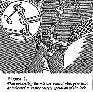
The two important factors in the choke adjustment are the synchronization of the choke levers, and the adjustment of the cable. The choke lever synchronization must be done first, and after any adjustments have been made to adjust the carb jets for correct normal operation. The movement of the two choke levers is synchronized such that the pull on the choke cable takes out all of the slack at points G and H at the same instant, which means that further pull on the choke cable will begin a pull down on the two carb jets at the same time. This synchronization is adjusted by adjustment of the two nuts; (4) on the threaded portion of the link (2). Adjustment of the link is best performed with the choke cable disconnected from the choke lever assembly. The cable can be disconnected by removing the cotter pin from the cable clamp (Figure 2) and withdrawing the clamp from the lever. Now the position of the two nuts on the link can be adjusted until the movement of the two levers in unison begins to move both carb jets at the same instant. With the movement of the choke levers correctly synchronized, the next step is to adjust the cable.
The choke cable adjustment is best performed by “trial and error.” That is, make an adjustment, check the result, and if the result is not satisfactory, make the adjustment again. Before starting the adjustment procedure, be sure that the choke knob on the dashboard is pushed all the way in. With the inner cable inserted through the hole in its clamp, but with the clamping nut loose, grasp the end of the inner cable with a pair of pliers and pull down on the cable to remove all of the slack in the cable. At the same time, make sure that the clamp slides up the cable until the choke levers are just starting to move in the pivot holes G and H. Clamp the cable in this position. Now check the response to the choke knob, and you may need an assistant for this. Pull the knob out a quarter to half an inch and see what affect, if any, it has had on the choke levers. Another half-inch on the choke knob should have started to move the levers to take up the slack at points G and H, and to have started to rotate the fast idle cam (item 1 in Figure 1). Pull the choke knob out another half inch, at which point the levers should have just started, or be about to start, pulling down on the carb jets. Another half to one inch on the choke knob should pull the carb jets down and expose about an eighth to a quarter of an inch of their shank below the mixture adjusting nut. Push the choke knob all of the way back in and the choke levers should return to their normal relaxed position, with the carb jets all the way back up so that the forked end is tight against the adjustment, and with no rotation on the fast idle cam.
If something like the above does not happen, then go back and reset the clamping of the choke cable. Adding another half-inch or so to the above description is probably OK, as long as the choke knob at its fullest extent does pull down on the carb jets and richen the mixture. If the choke knob comes out considerably further than that described above, then there is still too much slack in the cable. To remove some more slack, hold the end of the cable with pliers as previously described, and move the cable clamp up the cable another quarter of an inch, re-tighten, and then check the response to the choke knob again. Repeat the process until the required response to the choke knob is obtained, but be sure not to over do it to the point that the choke levers do not return all the way. Once again, the primary objective is to ensure that the carb jets are pulled down an eighth to a quarter of an inch when the choke knob is all the way out, and that the choke levers are in their normal relaxed position when the choke knob is all the way in.
Fast Idle Adjustment
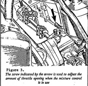
Once the choke cable is adjusted to your satisfaction, you can adjust the engine fast idle speed. As the choke knob is pulled out, about one half-inch of the edge of the fast idle cam should pass under the adjuster screw before the choke knob movement starts to act on the carb jets. Once the carb jets start to move, the fast idle cam should not rotate any further. At this point, using the adjuster screw, set the fast idle at 1200 to 1500rpm. Push the choke knob back in and make sure that the adjuster screw is clear of the cam and is not affecting the engine normal idle speed.
Finally, a few words on choke knobs and cables. The original choke knob was designed such that it could be locked in one of six or eight positions in its travel. This allowed the driver to set the choke at the optimum running position during engine warm up, depending on temperature and other conditions. The locking mechanism is a series of notches in the rigid shank behind the knob which are engaged by a spring-loaded (very tiny) tab in the housing. A slight clockwise twist of the choke knob disengages the tab and allows the knob to be pushed in without being held by the notches. Correct replacement cables also have a locking feature which is engaged by a slight clockwise twist of the knob. The normal position for the knob is with the “C” upright such that, for the original cable, the stops engage as the knob is pulled out. This is supposed to be assured by applying a clockwise twist to the end of the cable before clamping. However, it is my experience the knob will end up in its correct position without any special precautions. Besides, the is difficult enough to get the cable clamped in its correct position, without having to put a twist in it at the same time. However, if after all adjustment, your choke knob has a tendency to rotate into the wrong position, then carefully loosen the cable clamp and twist the cable in the appropriate direction. No more than one turn should be necessary. While making the twist, be sure that the cable clamp does not move up or down the cable in the process. Re-clamp the cable in the original position while holding the twist.
Many of the problems associated with adjusting the choke cable can be traced to the condition of the cable itself, usually kinks or fraying at the end. The original choke knob and cable assembly was still installed on our MGA, but the inner cable was not in good shape. I have replaced the original twisted strand inner cable with a single piece of steel wire of the same gauge. The wire did, however, require soldering into the back of the original choke knob, but the final result is a considerable improvement over the old bent and frayed wire.
Comment by: Joseph D. Mccurdy
I just rebuild my Dad’s carbs and had the same issue. I replaced each cork seals with two teflon o-rings. I found this on Barney Gaylord’s site.
McMaster Carr part number 9559K15. You will need 4 0-rings for each carb (total of 8). I still have some left, but have another set of carbs to rebuild for my car. The jets move much more freely and always seat appropriately now.
Comment by: Mike Ash
John, sorry for the delay, I was “across the pond”! I assume you are referring to the sticking jets, only, and the the piston continues to drop correctly. If that is the case, I think much of the problem is friction between the jet and its seals. The lubrication is only to ease assembly and to aid in seating the seals; it is soon washed away by the gasoline with use. Before assembly, I polish up the outside of the jets with a fine grit sand paper and steel wool, which seems to reduce this friction considerably. This not only makes it easier to pull the jets down with the cable, but it facilitates their return by the return springs. I have done this on all of my MGs, and it does seem to have made choke operation much easier, as well preventing hang-ups on return. I hope this helps. Mike.
Comment by: Peter & Anne Tilbury
Hi John,
We have forwarded your enquiry to Mike Ash who might have a solution to your sticking jet problem. Hope this will help you. Thanks for visiting NAMGAR.com.
Peter and Anne.
Comment by: John D. Welch
John,
I appreciate your explanation here, but, my question is, “How do you keep the jets from sticking?” I’ve set and reset the jets making sure that the needle is free and clear and that the piston drops correctly. However once I get the jet adjustment nut tight, the jets stick when the cloke is pulled out. The kit I have installed right now contained the cork O-rings for the jets. I soaked these in light oil overnight but still have the sticking problem.