Improving MGA Electrical Performance and Integrity
Mar/April 2024 V49/N04
As with most things, the devil is in the details; the little things can make a big difference. Early experimentation and observation of electricity in the 1600s indicated that positively charged objects moved toward negatively charged objects leading to the theory that current flows positive to negative. However, when electrons were discovered in 1897, they were found to be negatively charged and moved toward positive charges. This new discovery proved that current actually flows negative to positive. This presented a problem because over the previous two to three hundred years, much had been written about electricity; descriptions, terms and definitions had been long established so instead of rewriting history, so to speak, the easy resolution was to use the term “Conventional Flow” for the old view and “Electron Flow” for the new discovery. Widespread acceptance and design changes took years, even today, when we describe and discuss circuits, we generally use “Conventional Terminology”, but in designing or trouble shooting circuits we think “Electron Flow”.
Starting and charging systems were first invented in the 1920s. They were designed using “Conventional Theory” and were 6-volt with a positive ground. Most auto makers changed to negative ground when they changed from 6 to 12-voltbatteries.
We know that for an electrical device to work, current must leave one pole of a power source, travel through the device and return to the other pole of the power source, following the path of least resistance.
So, which pole is more important? If you think both are equally important, you are correct. So why aren’t they treated equally in the automotive industry? Using the frame and body as a conductor is cheaper than adding more wires. For decades, this method was good enough to get most vehicles through their warranty. It was strictly a financial decision. I cannot think of any appliance, device, tool or machinery that uses the frame to carry current. In household systems, for example, you have a hot wire, a neutral (circuit return) and ground (safety), which is connected to neutral at the power box and to the earth through a grounding rod.
Ground has a specific meaning but this term is often used in a very general way, describing anything connected to the return side of a power source. Ground connections are connected to the earth for safety. Return, completes a circuit(the signal return path) and is usually “grounded” for safety. It’s important to remember the difference and treat the circuit return with the same importance and integrity as the circuit source.
The nuts and bolts of it.
All electrical connections have some amount of resistance; wires, terminals, contacts, mechanical hardware, anything that connects one part of a circuit to another. All connections corrode, oxidize or tarnish and these oxidized compounds are resistive which in turn, cause a voltage drop. Electrical contacts and connectors are made to resist corrosion and maintain connection integrity. On the other hand, bolts, though conductive, are not designed for electrical integrity nor are they ideal conductors.
Let’s investigate the circuits in our MGAs. The battery power is connected by wires (a controlled path) to all electrical devices and components. The battery is connected to the frame by a heavy cable and the frame is connected to the engine block with a heavy braided cable.
The component returns are sometimes connected directly to the painted frame through bolts or wires. However, most components are connected to the painted body through bolts and wires. The painted body sits on cork or rubber pads on the painted frame, making it electrically isolated from the frame. Sometimes the paint gets scratched to bare metal and sometimes a bolt will touch the edge of the hole in both the body and frame. These are called accidental grounds(accidental return connections), not specifically designed connections. With over 30 body-to-frame bolts and about a dozen dash-to-body bolts, odds are it will get a connection somewhere.
Over time, the current flowing through these accidental connections will encourage corrosion, raising resistance, dropping voltage and will start causing electrical issues. The corrosion can be either galvanic (requires moisture and mineral salts) or electrolytic (requires energy). The speed and amount will depend on the environment (minerals, moisture, salts and so forth). When the resistance gets higher than the next accidental connection the current will split or move entirely to a lesser resistant connection. This random current path, while not ideal, is not harmful to DC passive components if the resistance is extremely low, but when we start adding active electronic components (radio, electronic ignition, LED lights and controllers) the electrical path becomes very important. Signals above 300 – 500 hz begin transmitting and receiving noise because the entire circuit and the relationship to the return path becomes an antenna tuned by the physical area between signal and return. This is why we have twisted pairs, coax and ribbon cables; each keeps the area between signal and return to a minimum and with coax and two wire flat cables, the distance is tuned to a particular bandwidth. The best practice for functional integrity is to run a dedicated return wire to each component that has power.
 Okay, how do we improve the MGA electrically? Treat each electrical component / device as if it were the only one in the vehicle by controlling the return to each component.
1. Make sure the battery connection to the frame is clean and down to bare metal. Make sure to use an external tooth star washer between the frame and the cable to the battery. This type of washer digs into both the frame metal and the terminal.
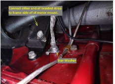
2. Make sure the engine return point is clean then place an external tooth star washer between the engine block and the “ground cable.” Do the same for the other end of the “ground cable” placing the tooth star washer on the frame side of the engine mount (not on top of the mount or on the front plate).
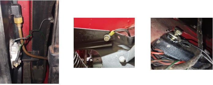
3. Optional – Remove the mounting bolt for the flasher unit (this is where the harness returns are connected), remove the paint from around the hole outside and inside the panel, replace the bolt with a 1 ½” 5/16 threaded stud (you can cut the threads off a long 5/16 bolt). Assemble with an external tooth star washer and nut on each side of the panel. This allows adding or removing connections on one side without disturbing the other and it also insures the “harness ground”connections on both sides have a solid connection to each other.
4. Find a threaded hole on the goal post (frame) inside the car, under the dash, clean to bare metal around the hole, then add a 14ga wire from there to flasher unit bolt inside the car. This connects the frame, body, and all the component and harness returns to a single point that goes directly to the battery with minimal connections.

5. Find the cable mounting tab welded to the frame over the right rear axle and clean it to bare metal. Then run a wire from that tab to one of the screws mounting the fuel sender unit (using star washers as described above) or run a wire from the rear “harness ground” to the fuel sender. Originally, the fuel line from tank to fuel pump was steel and the fuel pump return was a wire from the fuel pump to the frame. The tank is isolated from the frame by paint and rubber buffer strips between the tank and painted mounting straps so the return for the fuel sender is through the mounting screws to the tank which is connected through the fuel line to the fuel pump and the pump return wire to the frame. If the fuel line has been cut to add a plastic fuel filter or rubber fuel line repair, the sender unit is no longer connected to the gage.

6. Remove one of the frame-extension mounting bolts and clean the frame (not the extension) to bare metal, add a wire from there to the body mounting bolt that has the front “harness grounds” connected to it (again using the star washers).
7. Make sure the rear “harness ground” connection is clean and a star washer is used between frame and terminal.
Now the current flow is no longer random or accidental. The current flowing through frame,body and mechanical hardware is minimal. As a result, integrity is greatly improved.
If you treat source and return with equal importance, purpose, and connection integrity, your electrical issues will be greatly reduced and limited to actual component failure. You will spend fewer sunny days sorting out electrical issues and more on the road.
Written by Bob Shafto, October 2023.

