
Generator Service

VOL 18/NUMBER 2
 The oft forgotten oiling point on the MGA is the bush at the rear of the generator. If neglected, the bush can wear and, if ignored too long, this can result in damage to the armature or the field coil. In this Tech Session from MGA! Vol. 18/No 2, Mike Ash describes the generator service, operation, disassembly and repair.
Generator Service
I did have to check out a problem with a generator and replace the rear bushing, so maybe that experience will be of interest to someone out there in MGAland. I have entitled this topic “Generator Service” rather than “rebuild” because the most common causes of MGA generator failure are the brushes and the rear bushing; both of which are relatively easy to fix. There are other causes of generator failure that can be remedied by a complete rebuild, but these are not easily diagnosed or corrected without specialized equipment.
This particular generator was not charging, and all of the “by-the-book” checks indicated that the generator was the culprit. It turned out that the brushes were in good shape but, since the generator had been lying around unused for some years, the brushes were tight in their housings so that the spring pressure could not easily keep them in contact with the commutator. That problem was easily solved, but while I had the generator apart I noticed that the rear bushing was in hurting shape.
Generator Operation
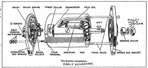
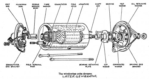
Before I get into the disassembly, an overall description of the generator (or dynamo, as they say in England) may make things a little clearer. The shop manual provides an excellent picture as a basis for the description. The generator has four primary components: commutator end (rear) bracket, armature, field housing (or yoke), and driving end (front) bracket. To generate the electricity, the armature, driven by the fan belt, rotates within the housing. The stationary magnetic field generated by the field coils induces an electric current in the windings of the armature. The induced electric current is “extracted” from the rotating armature by carbon brushes in contact with the copper segments of the commutator at the rear of the armature.
The voltage regulator controls the strength of the magnetic field generated by the field coils, which in turn controls the amount of current available at the brushes. The brushes are connected to the output terminal on the generator, which is connected to the “D” terminal on the voltage regulator. The armature rotates inside the field housing on a ball bearing race in the center of the front bracket and a bronze bushing in the center of the rear bracket. The two end brackets are attached to the ends of the field housing by two long bolts, which pass through the front bracket and the housing,and are threaded into the rear bracket.
Generator Disassemble
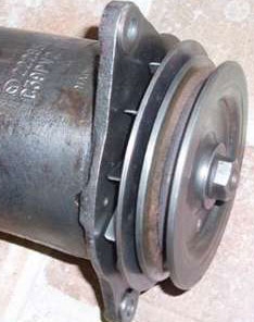
With the generator removed from the car, the first step is to remove the pulley from the front. The pulley is attached by a large nut threaded onto the armature shaft. The nut will (should) be tight and the pulley can be held from rotating with a large pair of channel-lock pliers, or a fan belt wrapped in the pulley groove. Under the nut there should be a large split or serrated lock washer. With the nut and washer removed, the pulley can be pulled off the shaft. It may slide off easily, or you may need a gear puller. Whatever method you use to remove the pulley, be sure not to damage the pulley or its fan. The pulley is keyed to the shaft and is generally separate from the fan. After the pulley and fan are removed, tap the key out of its groove in the shaft using a small screwdriver. Remove the nut and washers from the field terminal at the rear of the generator.
To disassemble the generator itself, slacken and remove the two long fixing bolts. These bolts are counter-sunk into the face of the front bracket, and have a screwdriver slot. Use a large screwdriver to avoid damage to the slotted head. Withdraw the screws and pull the rear bracket away from the housing and off the end of the armature. When you do this, you will probably hear a “click” as the brushes come off the end of the commutator and their springs push them toward the center. Next, carefully pull the housing off from over the armature, leaving the armature attached to the front bracket.
Examining the Components
As I said above, the two easiest areas to service are the brushes and the commutator, both of which are attached to the rear bracket. In operation, the brushes are held in their holders and in contact with the commutator by the pressure of the springs. The position of the commutator is such that, when in contact, the brushes just protrude from the inner side of their holder, and a new brush will protrude about an eighth to a quarter inch from the outer side of the holder. As the surface of the brush in contact with the commutator wears, the spring pressure feeds the brush through the holder until eventually (probably a couple of hundred thousand miles) the outer edge of the brush sinks below the level of the edge of the holder and the spring can no longer exert any pressure on it.
Examine the brushes for wear by comparing their length with the “length” of the holder. If the brushes are less than an eighth of an inch longer than the holder, they should be replaced. They should also be replaced if there is any sign of chipping or other damage to the edge that is in contact with the commutator. Remove the brushes by moving the spring out of the way, sliding the brush out of its holder; and disconnecting the lead from the screw terminal.
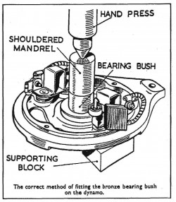
Next, examine the bronze bushing that is pressed into the center of the rear bracket. The inside will probably look slightly oval, with signs of wear to one side. If the bushing shows obvious wear, (and it may well be worn completely through on one side), it should be replaced. The shop manual says to press out the bushing but, since it is in a blind hole, that is easier said than done. Since the bronze material with which the bushing is made is quite thin and brittle, I find it easiest to gently chip away at the old bushing with a hammer and small sharp chisel. Cutting a couple of longitudinal grooves in the inside of the bushing with a piece of a hacksaw blade also helps.
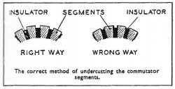
After checking the brushes and the rear bushing, examine their counterparts on the armature. The commutator should be a clean, copper color, but will probably be discolored with black streaks from the action of the brushes, and there may be some scoring. Clamp the armature gently in a vise and clean up the commutator surface with fine sandpaper until it is a bright copper color. Examine the commutator for signs of damage. Some scoring will not hurt as long as it is not too deep. If any of the commutator segments are loose, or if any wires from the armature winding have become unsoldered or detached, the entire armature is not usable. After cleaning up the commutator, clean out the insulation grooves between the commutator segments with a hacksaw blade. I am not sure that this is as critical as the shop manual suggests, as long as the insulation is below the level of the commutator segment faces.
 Examine the stub end of the armature shaft that runs in the rear bushing. It too may be scored, possibly deeply if the rear bushing had worn completely through. If necessary, clean the shaft up with fine sandpaper to remove any rough spots. Again, some scoring will not do any harm.
The front bracket should still be attached to the shaft at the front end of the armature. Check the bearing by spinning the bracket on the shaft and listening for any significant noise or roughness. Also check for any looseness in the bearing itself. The front bearing does not normally wear out and need replacing.
If it is worn out, the front bracket must be pressed off the shaft and the bearing removed by drilling out the rivets in the front bracket that secure the bearing retaining plate. You may want to entrust this activity to a competent machine shop or generator rebuilding service.
Cleanup and Re-Assembly
Clean up all the pieces as best you can without immersing the field coils or armature windings in any cleaning fluid. If available, use a compressed air gun to blow out any dust or dirt in the field and commutator windings. Press the new bushing into the rear bracket, after soaking it in engine oil for about 24 hours to fill the pores in the bronze with oil. Fit the new, or re-fit the old, brushes into their holders and attach the leads by the terminal screws. Make sure that the brushes are an easy sliding fit in their holders by, if necessary, gently filing the brush or holder. Position the brushes in the holders so that the inner ends that run on the commutator are NOT protruding from the holder. Lock them in this position by wedging the spring against the exposed other end of the brush. This will temporarily secure the brushes clear of the commutator for re-assembly. Remove the distance collar from the front of the shaft to expose the front bearing, and pack the bearing with a high melting point grease. With the frontend bracket still attached, or re-attached, to the front of the armature shaft, you are now ready to assemble the complete generator.
 Slide the field coil housing over the armature and up to the frontend bracket. Note that there is a small notch in the front edge of the housing that engages with a small peg set into the rim of the front bracket. If the peg is missing, which is not unusual, locate the hole in the rim of the bracket where the peg was and align the hole with the notch in the housing. Insert the two long fixing bolts through their holes in the front end bracket and on straight through the housing. Slide the fiber thrust collar onto the rear end of the armature shaft, followed by the rear end bracket. Be sure that the brushes are firmly held clear of the commutator. The terminal of the field coil must pass through this bracket, the peg in the rim of the bracket must locate in the notch in the housing and the threaded ends of the two fixing bolts must enter the threaded holes in the end bracket. With everything in position, fully tighten the fixing bolts.
Attach the appropriate nuts and washers to the field terminal and the “D” terminal. Slide the distance collar over the front end of the shaft, and up to the front bearing. Place the key in its slot, push the fan and pulley onto the shaft, and secure with the locking washer and nut. Make sure the nut is really tight. If it comes loose, the pulley can wobble slightly on the shaft, which will eventually cause considerable, and expensive, damage to the shaft and pulley. That completes the re-assembly, except for setting the brushes. The early generators had a window, as shown in the diagram, in each side of the field housing to provide easy access to the brushes. The later generators provided more restricted access to the brushes through holes in the end bracket. Which ever type you have, poke around through the hole with a screwdriver or similar tool to move the end of the spring from its wedged position at the side of the brush to the top of the brush. Make sure the end of each spring is resting neatly on the top of each brush to hold the other end of the brush in contact with the commutator.
Install the generator on the car, and adjust its position to tighten the fan belt. Do not over tighten the fan belt. An over tight belt will considerably shorten the life of the generator rear bushing, as well as place undue strain on the water pump bearings. It is very important to use the correct fan belt, both in length and width. The V-shaped belt should ride on the edges of the V-grooves in the pulleys to provide the friction to drive the pulleys. If the belt is badly worn, or incorrect, so that it rides in the bottom of the pulley grooves, it should be replaced with the correct belt. The belt should be sufficiently tight so that it will drive the water pump and generator without slipping. The belt is tight enough if the fan can be rotated by hand, but with appreciable resistance. When on the car, the only required maintenance is to periodically check the tightness of the belt and to periodically lubricate the rear bushing with engine oil. The bushing is oiled through a hole in its housing in the center of the rear bracket. A felt pad behind the hole retains the oil.
Comment by: Anthony M Jachnycky
I assume you measure the performance of the generator via voltage meter across the poles on the back of the generator? If so what is the optimum voltage or range that it should be?
Comment by: David & Rita Houser
Mike,
Thanks for reminding me about this oft overlooked service.