
MGA! Tech Talk – January/February 2017

 As the years pass, MGAs and Magnettes have become much better cars, thanks to your efforts! You have made them more attractive, and more dependable. Think about these cars back in the 1970s. Most had sagging rocker panels and were hardly capable of making it across town without breaking down or running out of oil first!
As we strive to continually improve these cars, it seems there’s one little aspect that keeps raising a ruckus. It’s those pesky engine valves, or more specifically that clattering noise, which makes our sporty little pushrod cars sound like cheap sewing machines.
The pushrod MG engine relies on solid tappets (also called lifters or cam followers) that require a very specific amount of gap to be manually adjusted into the system. You’ve probably heard of hydraulic lifters, most common in American engines dating back to the 1930s. The advantage of hydraulic lifters is that they automatically maintain a near zero clearance, resulting in a very quiet engine. Think of your hydraulic clutch system for comparison, where the slave cylinder would represent a hydraulic lifter. In the same manner as a lifter, the slave cylinder bleeds off fluid when at rest to maintain a near zero clearance from the release bearing to the pressure plate. While hydraulic lifters could make our engines a lot quieter, there is no simple way to retrofit that type of lifter to the B-Series engine. And, hydraulic lifters are not perfect either. Besides being more expensive, they are not well suited to high-revving engines, and can fail.
On the flip side, if the clearance is set too wide, the valve will open for a shorter duration, resulting in a loss of power. Additionally, significant damage begins to occur to the camshaft and tappet. The cam now slams against the tappet to open it, which can halt the rotation of the tappet and lead to inevitable damage to the tappet and cam.
So, the gap really should be within .001” of whatever the specification. But what of the two numbers in the factory workshop manual when both the early and late MGA have virtually the same valve train? And just to make it interesting, the MGB manual states .013” with the engine warm! Here’s my take on the matter.
First of all, if you have some type of performance cam, go with the specification of that manufacturer. But if you are running a stock or mild road cam, or you think you may have an original camshaft, I recommend you bring the engine to operating temperature and set the gap at .013”. It’s okay if it cools some while you are making your adjustments. If you are setting up an engine that doesn’t run yet, go with .015” and recheck after 500 miles, using the warm procedure.
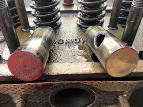
But the story doesn’t always end here. Now that you’ve spent time carefully adjusting all of your valves, you start the car and one or more tappets are making even more noise than before! The reason is, you likely have worn rocker arms, in particular the underside where they meet the valve. This is a common problem and throws off the accuracy of your valve adjustment.
When in operation, the face of the rocker pushes the valve open, and in doing so, slides across the tip-end of the valve, resulting in a nice little recessed wear pattern on the rocker face. When you attempt to adjust your valves by using a feeler gauge, the gauge is wider than the recessed area, and does not take account for what may be another few thousandths of an inch (or more) in clearance.
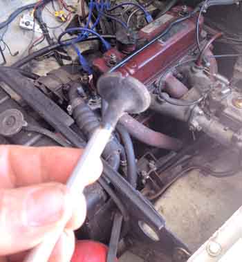
 A simple check of the condition is to remove the rocker cover, rotate the engine to where valve number seven is fully open. Then loosen the lock nut and adjuster screw on rocker number two. Once the adjuster is backed off to give maximum clearance, you can slide the #2 rocker rearward on the shaft and rotate it 180 degrees to expose the underside. Inspect the face for wear (see photo below on left).
You can do this for all but the front and rear rockers, as they have no place to slide and rotate. While each rocker is temporarily in the new position, you can feel the underside of the rocker shaft, where the rocker normally rides, for wear (see photo above right). If this or the rocker face indicates wear, it’s time to repair or replace the rocker assembly.
 To do the job, the shop manual recommends draining the coolant. Then loosen (if you haven’t already) the eight valve lash adjusters to take tension off the rocker shaft. Next, loosen the four 5/16” nuts on the rocker shaft about a half a turn. Again, referring to the shop manual, loosen ALL of the head bolts about a half turn, following the same pattern for tightening the head. (This is to prevent the cylinder head from warping.) You may then gradually remove the four 3/8” head nuts and the four 5/16” nuts that retain the rocker shaft. Do not remove the other head nuts! Remove the rocker assembly by lifting it straight up.
If you search the Internet, you will find most everyone agrees the hardened shaft will wear before the soft bronze bushings in the rocker, which seems backwards. Speculation is that the bushings will catch particulates from dirty oil, which embed in the soft bronze and act as sandpaper against the shaft. So, technically, the rocker bushings would be tight on a new shaft. But reusing the old bushings would result in the “sandpaper effect” starting right in on your new shaft.
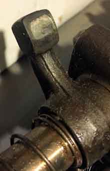
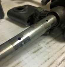
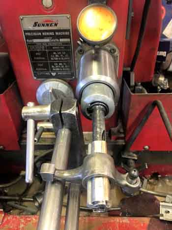
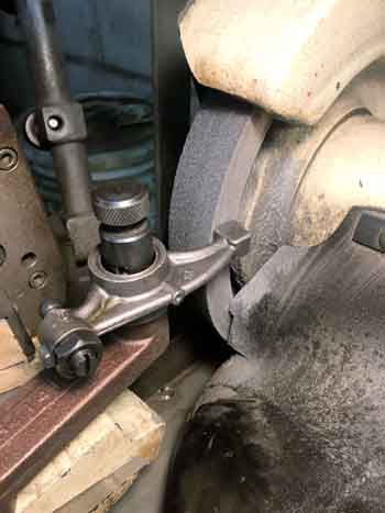 Complete replacement rocker assemblies with new shafts and bushings are available from several of our advertisers, and work well. Alternatively, a new shaft and new rockers are also available separately and can easily be assembled by you. But you still might consider rebuilding your existing rockers and fit a new tuftrided shaft. A machine shop can easily replace the bronze bushings and reface the tips (see photo left). The real advantage is that you retain the adjusters with the proper ball end for your car. There was a change in the ball and socket of the pushrod in early production of the B series motor. Also, I’ve seen where replacement rocker assemblies have a bit too much clearance when fitted to a new shaft. The running clearance should be .001”. If too tight, they will bind. If too loose, there will be oil pressure loss, as well as increased wear. A machine shop can properly ream your new bushings to give that proper clearance (see photo below left).
 Another reason for rebuilding your rockers is that some replacement rocker assemblies have eliminated the oil feed to the ball and socket area. And lastly, if you do go with a replacement rocker assembly, be sure to compare the base of the rear pedestal to your old assembly. The oil feed hole was located in the center of the pedestal on MGAs and early MGBs. But on later MGBs, the oil feed was moved to an offset position from the pedestal. Be sure to check yours for proper alignment!
Reassembly of the rocker shaft to the engine is straightforward, and well documented … with the exception of the actual valve adjustment as we already discussed. Since you will have to make an initial adjustment with the engine cold, I’d suggest going with .015” (unless you have different spec for your cam).
This exercise should result in the quietest sewing machine…I mean…MG on your block. Safety Fast!